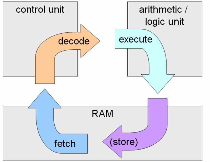
What a CPU does is execute the instructions of a program located in memory. But, did you know that they all follow the same general rules? They all follow the same instruction cycle, which is divided into three distinct stages called Fetch, Decode and Execute, which are translated as fetch, decode and execute. We explain how these stages work and how they are organized.
In order to simplify and make the concepts explained in this article more understandable, we have decided to describe an extremely simple processor for current times, so in this article you will see an explanation of what instruction cycles are in a generalized way that can be apply from the first 8-bit processors to the most complex ones available today
These three stages are fulfilled in every processor. There is a fourth stage, which is Write-Back, which is when the execution units write the result, but this is usually counted within the execution stage of the instruction cycle.
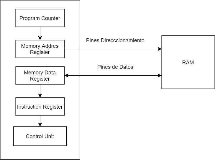
The first stage of the instruction cycle is responsible for capturing the instructions in the RAM memory assigned to the processor through a series of units and registers that are the following:
These 4 sub-stages occur in all processors whatever their utility, architecture and binary compatibility or what we call ISA.
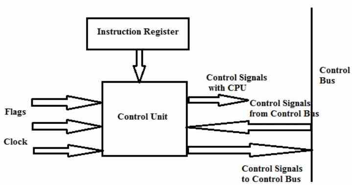
The control unit is the most complex part that exists in a processor and its tasks are as follows:
What the control unit does is decode the instructions and it does this because each instruction is actually a kind of sentence where the verb goes first and then the direct object or object on which the action is done. The subject ends up being eliminated in this internal language of computers by the fact that it is understood that it is the computer itself that executes it, so each number of bits is a sentence where the first 1 and 0 correspond to the action and the ones that come next is the data or the location of the data to be manipulated.
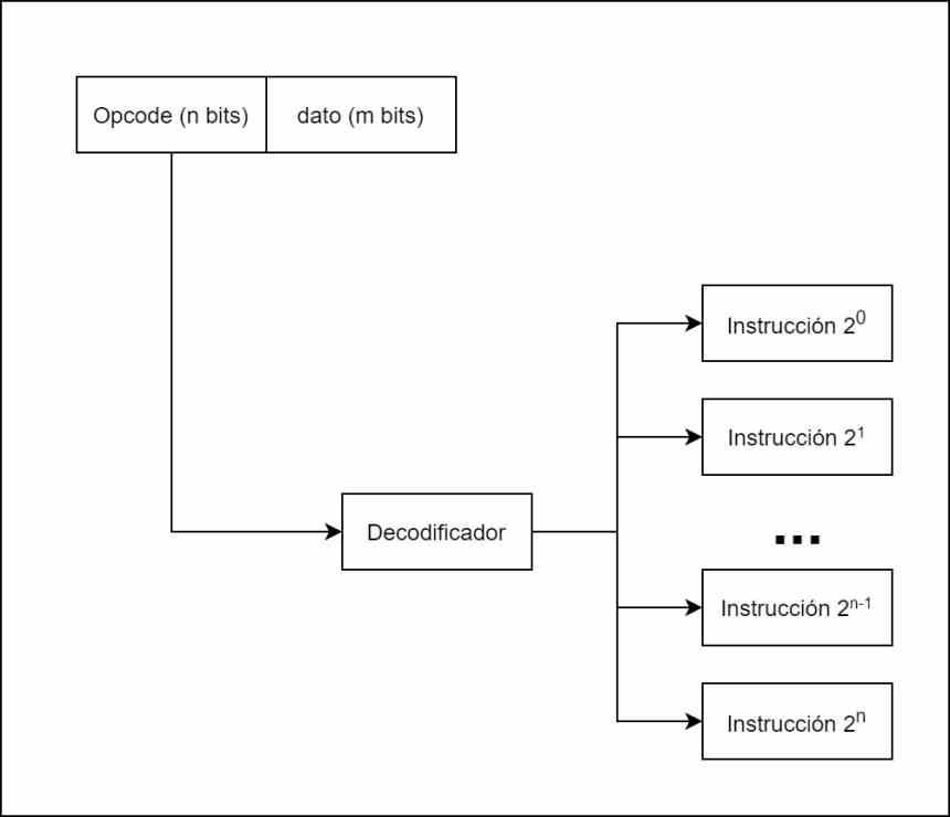
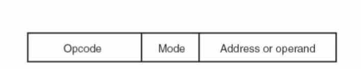
There are different types of instructions and not all of them do the same, so depending on the type of instruction we need to know what execution units are going to be sent to and the most classic way of doing it is through what we call a decoder, which takes each instruction, divides it internally according to the opcode or instruction and the data or memory address where it is located.
For example in the diagram above we have the diagram of a processor with only 8 instructions, which can be encoded in only 3 bits. Each one of the instructions, once decoded, is sent to the different execution units that will resolve them.

This instruction cycle is the most complex of all and the one that defines the type of architecture. Depending on whether we have a reduced or complex set of instructions, this will affect the nature of the control unit, depending on the format of the instruction or how many are processed at the same time the decoding phase and therefore the control unit will have a different nature. other.
The easiest way to visualize what happens is to think of the instructions as trains circulating through a complex railway network and the control unit directing them to a terminal station, which is the execution unit that will be in charge of solving the instruction.
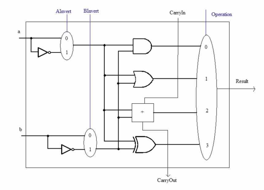
The other point is the instruction formats, since an instruction can be applied to a data, scalar or several data at the same time, which we know as SIMD. To finish and depending on the data format, there are different types of ALUs for the execution of arithmetic instructions, for example we have integer and floating point units as differentiated units today.
Once the instruction has been completed, the result is written to a specific memory address and the next one is executed. Some instructions do not manipulate memory values but rather certain registers. Thus, the program counter register is modified by the jump instructions, if we want to read or write data then the MAR and MDR registers are manipulated.